It is important to model case studies and use them for validating applications in cyber-physical power systems. Examples include cyber-physical contingency and sensitivity analysis. The aim is to effectively utilize the information from both cyber and physical assets to achieve deep cyber-physical situational awareness of the power system.
The objective with these cyber-physical grid models is to manageably represent the system to enable analysis such as how the power system, cyber network topology, and interconnections impact the operational reliability of the power system through access to its physical assets, represented in a detailed node-breaker model. Using these synthetic models, we employ modular designs that contain defined fields, functions and interfaces, to emulate the cyber-physical power network. These models are designed to be sharable and to enable repeatable research in power system cyber-physical analysis.
8-substation Model
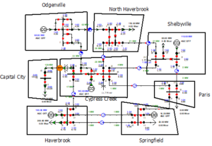
Explore the 8-substation cyber-physical power system case to understand the important objects and fields in these models. The information in these cases is useful to allow people as well as tools to discover and prioritize what is important for achieving power system cyber-physical resilience.
24-substation Model
Explore the 24-substation cyber-physical power system case to understand the important objects and fields in these models. The information in these cases is useful to allow people as well as tools to discover and prioritize what is important for achieving power system cyber-physical resilience.
300-substation Model
Explore the 300-substation cyber-physical power system case power system case to understand the important objects and fields in these models. The information in these cases is useful to allow people as well as tools to discover and prioritize what is important for achieving power system cyber-physical resilience.
TX-CP-2000 Model
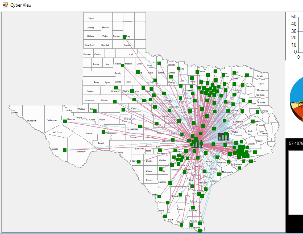
In this Texas CP-2000 dataset, the cyber components of this power system case have been created following the communication model adopted by a regional reliability coordinator in interacting with the electric utilities or the market participants (i.e., a scheduling entity (QSE), load-serving entity (LSE), resource entity (RE), or transmission/distribution service provider (TDSP)). The communication model is hierarchical based on having 3 primary levels: Level 1: Balancing Authorities, Level 2: Utility control center (UCC), and Level 3: Substations as shown in the figure below. The geographical location of the substations in the power system test case is considered to determine the geographical location of the utility control center using K-mean clustering. The green-colored icons in the map represent the location of the UCCs in the communication network.

Physical
The physical model defines the topology (bus-branch or node-breaker), component models (including transformers, generator’s transient stability models including governor and exciter, load model, transmission line parameters, Y matrix, etc.). The communication or the cyber model defines the networking devices that support the power system’s operation at transmission, generation, and distribution levels. Our synthetic communication model defines the model for routers, switches, firewalls, EMS servers, DNP3 Master, ICCP servers, etc as nodes. The links in the model represent the communication channel types such as microwave links, Ethernet, or MPLS/fiber links. DNP3 is the communication protocol used for communication between UCC and substation (and also within substation). ICCP is used to communicate between Balancing authorities and UCC. The interconnection between the cyber and physical subsystem models is through substation intelligent electronic devices, such as remote terminal unit, protective relays, automatic controllers, etc., which directly connect and control physical system and supply data in cyber network. We use the CyPRES tool to generate the visualization of the synthetic communication network, and we export the model in the form of JSON objects defining each component.
Interconnections
In our comprehensive cyber-physical model, we use protective relays as the cyber-physical interconnection to connect the cyber and the physical subsystem models. Each relay in a substation has an IP address from cyber network and protects a specific branch through controlling circuit breakers in the physical system. In our detailed node-breaker power system topology, there are circuit breakers and disconnects to represent the complete information within each substation.
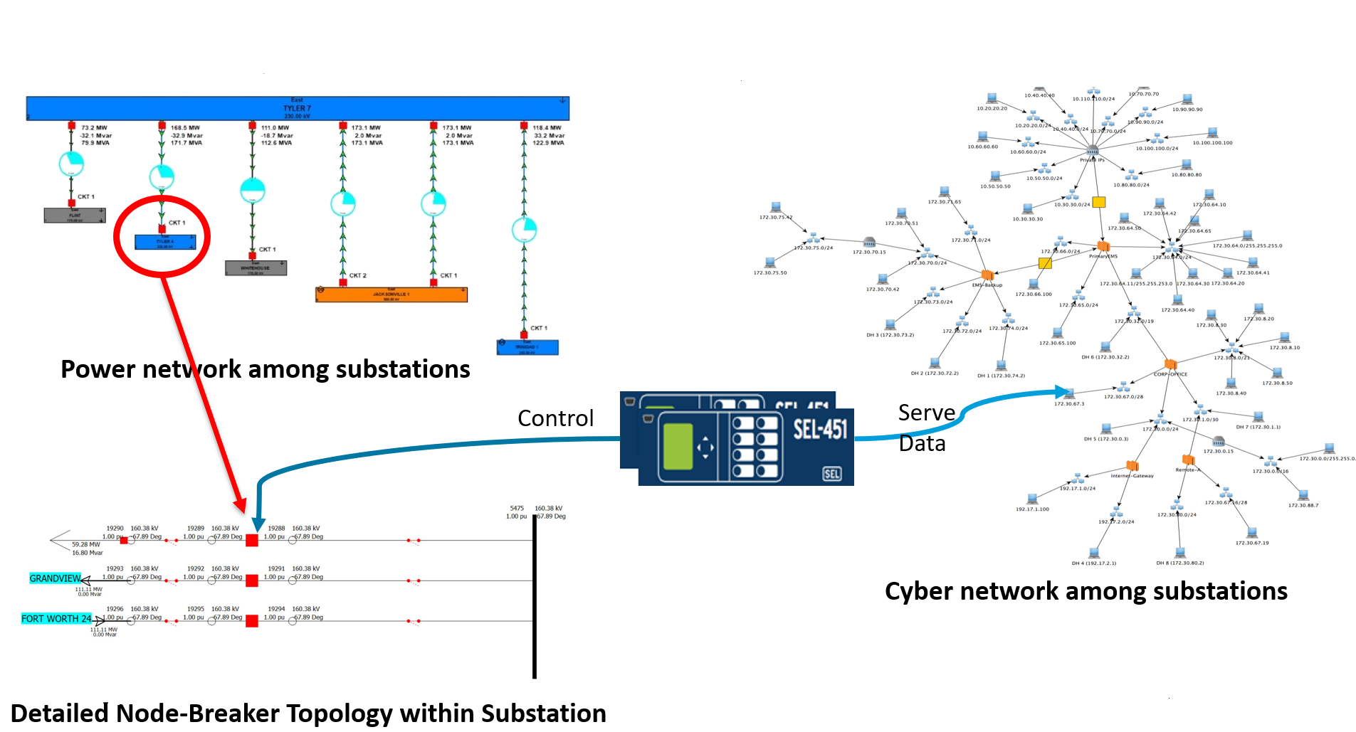
To achieve the node-breaker model, based on bus nominal voltage, we expand the bus topology to Single Bus Topology for bus nominal voltage is under 200 kV and Ring Bus Toplogy for bus nominal voltage is over 200 kV, which inserts bus nodes to extend the bus-branch model to a node-breaker model capable of representing more detailed substations and cyber-physical scenarios. To run power system simulations smoothly and integrate with the cyber network efficiently, we build and maintain a map that connects bus-branch model with node-breaker model. In this way, it is possible to simultaneously use the coarser-grained bus-branch model to serve power system data to the cyber network through the DNP3 protocol, while the detailed node-breaker model can be used to study the physical impact, considering specific devices and substation configurations.
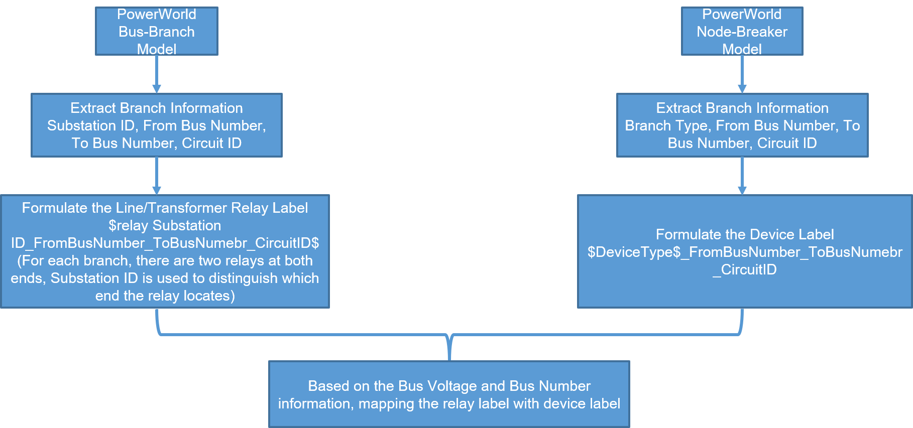
For buses expanded using our Single Bus Topology layout, in each resulting substation, one relay controls one circuit breaker along with two disconnects. As seen in the following example, the Relay Label uses information from the bus-branch model to identify its location in a substation and which branch it should protect in bus-branch model. In following columns, the Power System Element shows the corresponding branch in the node-breaker model that is protected with the Protective Devices which comprise one circuit breaker and two disconnects.
Relay at From Substation

Relay at To Substation

DNP3 Outstation Incorporation
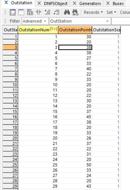
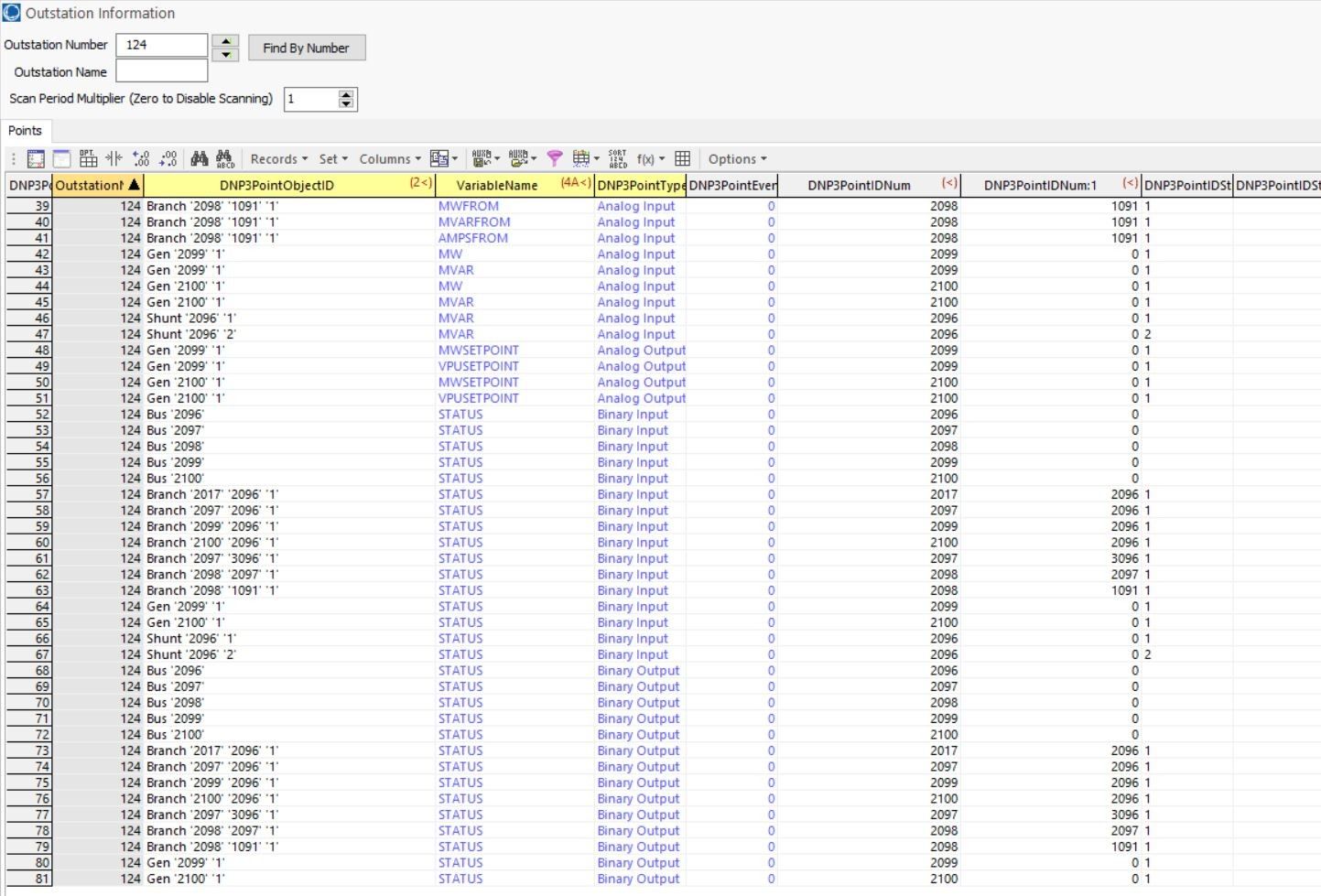
For each substation in our Texas 2000 bus case, we created DNP3 outstations for each substation in bus-branch model based on the Substation ID. In the bus-branch model, only the bus has the attributes of which substation it is locates at. Based on that, we group generators, loads, shunts and branches into each outstation. Within each DNP3 outstation, we create Analog Input (AI), Analog Output (AO), Binary Input (BI), and Binary Output (BO) tags for bus, branch, generator, load and shunt.
For AI, if the substation has the devices, we insert the following tags.
- Bus: voltage, frequency, voltage angle and voltage in per unit;
- Branch: real power flow, reactive power flow, and current;
- Generator: real power output and reactive power output;
- Load: real power and reactive power;
- Shunt: reactive power.
For AO, since PowerWorld DS only supports analog control for generator real power setpoint and voltage setpoint, we insert AO tags only for generators. In the future, we might add the load MW as a controllable variable, which represents the ability to do partial load shedding, as well as the tap ratio for transformers.
- Generator: real power setpoint and voltage magnitude setpoint.
For BI, if the substation has the devices, we insert Status tags for bus, branch, generator, load and shunt to inform what status they are (On/Off).
For BO, if the substation has the devices, we insert Control tags for bus, branch, generator, load and shunt to control their status (On/Off).
Here is an example of our DNP3 outstations and DNP3 tags.

Citations:
- P. Wlazlo et al., “A Cyber Topology Model for the Texas 2000 Synthetic Electric Power Grid,” 2019 Principles, Systems and Applications of IP Telecommunications (IPTComm), Chicago, IL, USA, 2019, pp. 1-8, doi: 10.1109/IPTCOMM.2019.8921260. https://ieeexplore.ieee.org/abstract/document/8921260
- N. Gaudet, A. Sahu, A. E. Goulart, E. Rogers and K. Davis, “Firewall Configuration and Path Analysis for SmartGrid Networks,” 2020 IEEE International Workshop Technical Committee on Communications Quality and Reliability (CQR), Stevenson, WA, USA, 2020, pp. 1-6, doi: 10.1109/CQR47547.2020.9101400. https://ieeexplore.ieee.org/abstract/document/9101400
Files to Download:
- PowerWorld latest case (with the relay models and DNP3 outstations, include both node-breaker and bus-branch versions)
- JSON files for the synthetic communication model, (will attach the synthetic firewall configs).
